
ASSIGNMENT
For this assignment, we had to produce one soft sensor experimenting with the materials available at our local Fablab. Also, if possible, we should try to reproduce the same sensor with different materials and/or techniques (hard/hard hard/soft soft/soft). For a more advanced assignment, we could program an ATTINY and ass it to the circuit. I chose to go for the ADVANCED, but starting from the EASY and going step by step.
INSPIRATION
My inspiration for this assignment were the Mexican Calaveras. Because the assignment date would fall close to Dia de los Muertos, which is a big celebration in Mexico, I thought it would be fun to make something culturally relevant. In Yucatan, the Mayan tradition calls this day Hanal Pichan, which translates to "Food of Souls". It's been really exciting to see all the preparations for this event gaining momentum in Merida.

Foto credits: Left, decalaveras.com; Center, Jose' Acosta/IPSE; Right, cronicadelpoder.com
OBJECTIVES & PLAN
The objective for this assignment is to create a basic circuit at first, with no coding involved, and then move to a more complex one involving the programming of the ATTINY. In order to achieve so, I plan to do the following:
- Create a pressure sensor with Velostat
- Find and tweak Arduino code to evaluate the pressure sensitivity of the pressure sensor
- Build a circuit that fades in LEDs according to pressure intensity
- Assemble the calavera with the circuit
- Program an ATTINY
- Add it to my e-calavera circuit

INTRO TO E-TEXTILES
This class focused on exploring how we can produce soft circuits and sensors, to embed them into garments and wearables, using soft circuits and soft actuators. The class was given by Kobakant, e-textile creative duo composed by Hannah Perner-Wilson and Mika Satomi, who shared a thorough overview of materials , components, tools and projects in the realm of e-textiles.
So, what are e-textiles?
E-textiles, also known as electronic textiles or smart textiles, are fabrics that enable digital components (including small computers), and electronics to be embedded in them.
E-textiles can be divided into two main types:
E-textiles with classical electronic devices such as conductors, integrated circuits, LEDs, and conventional batteries embedded into garments.
E-textiles with electronics integrated directly into the textile substrates. This can include either passive electronics such as conductors and resistors or active components like transistors, diodes, and solar cells.

STEP 1. Wrap copper tape around the thick paper
STEP 2. Use double sided tape to attach the Velostat to the paper

STEP 3. Ta-dahh! They are connected. Ready for testing
MAKING THE PRESSURE SENSOR
I created the pressure sensor taking into account this, this and this tutorial. Here's how it went
INGREDIENTS
- Velostat sheets
- Copper Tape
- Thick Paper
- Double sided tape
- Alligator clips
- LED
- Battery holder + coin cell battery
PROCEDURE
- I decided that I wanted to be able to squeeze the calavera to make the LEDs brighter. So I decided to make them as big as my palm
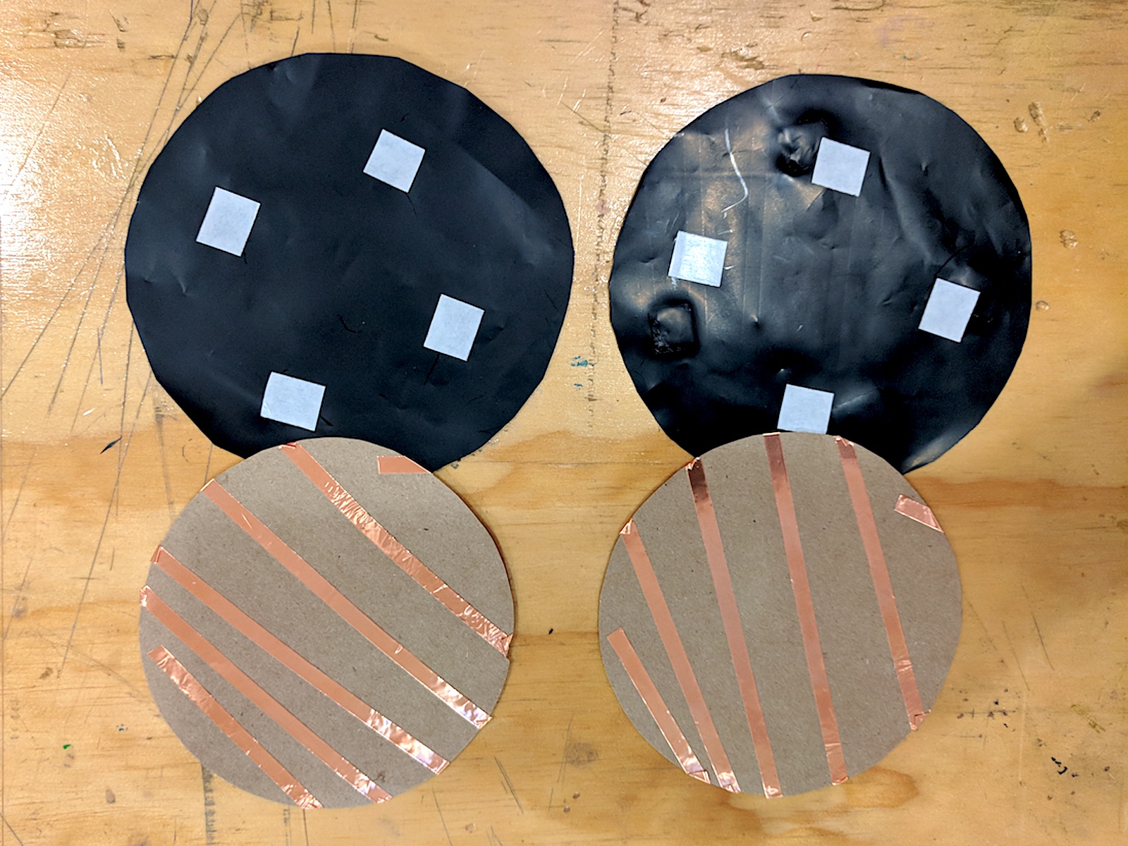
- I cut 2 circles in thick brown paper, with a diameter of 11 cm
- Then I wrapped the copper tape around each one, ensuring it didn't make contact with itself at the edges
- With the Velostat, I made 2 circles as well, but with the diameter 12 cm, in order to insulate the copper circles on from the other and make sure they don't touch each other
- I then put together the simple circuit pressure sensor + LED with alligator clips and tested its functioning
RESULTS & REFLECTIONS
- The pressure sensor worked successfully to turn the LED ON & OFF.
- I tried if it still worked if the pressure sensor was wrapped around my wrist, i.e. squeezing it, and it also worked.
- The Velostat pressure sensor works well in providing an input with a digital output (ON/OFF).

PROGRAMMING ARDUINO
At this point I wanted to see how well could the pressure sensor read analog values as well as the digital ones. My goal was to increase the light intensity as I increase the pressure on the Velostat pressure sensor. I used this tutorial suggested by Zoe Romano, and created by John Thomson.
INGREDIENTS
- Lilypad Board / then Arduino UNO
- Alligator clips
- Hookup wires
- Breadboard
- Resistors to make a 220 Ohm resistance (2x100Ohm + 2x10Ohm)
PROCEDURE
I put the circuit together on the breadboard, being careful to put the resistors in series. When you put resistors in series, the result is the sum of each resistor. Because we didn't have a 220Ohm resistor at the Fablab, I used 2x100 Ohm resistors and 2x10 Ohm resistors. Find more info on resistors in series vs in parallel here .
I compiled the code below on Arduino and tried to upload it to my Lilypad.
int sensorPin = A0; //select input for the potentiometer
int ledPin = 9; //select output for the LED
int sensorValue = 0; //variable to store the value of the sensor

void setup()
{
 //Declare LED as the output
  Serial.begin(9600);
  pinMode(ledPin, OUTPUT);
  //pinMode(sensorPin, INPUT);
}

void loop()
//read the value from the sensor
{
sensorValue = analogRead(sensorPin);
Serial.println(sensorValue);
if(sensorValue>366)
{
  digitalWrite(ledPin, HIGH);
}
else
{
  digitalWrite(ledPin, LOW);
}
//delay(30);
}
NOTE: There was no way to upload the code on the Lilypad. I got this error:
avrdude: stk500_recv: programmer is not responding

Note for the readers: I am aware that the Lilypad selected in the Arduino screen here is the USB, but I tried also with the regular Lilypad Arduino, with the same exact results.
On the Arduino IDE I checked the Tools > Board > Lilypad - it was correct. I also checked the Tools > Port > the port was also correct. I looked for toubleshooting answers online and found that on the newer Macs OS, the FTDI drivers are overridden, making it a challenge to connect to the Lilypad. So I followed the instructions I found on Sparkfun to install the right drivers and dismiss the ones installed automatically on Mac (versions Maverick and beyond).

After trying all the possible avenues and downloading the scripts, dismissing the Mac scripts and also trying to use the Arduino Web Editor, I decided to use an Arduino UNO, to avoid having the problem. The UNO worked immediately and I decided to use the Arduino Web Editor to evaluate it's usability vs the IDE.
TESTING / 1 - Analog INPUT && Digital OUTPUT
I had to adjust the values of the threshold on the Arduino by checking the values on Serial Monitor.
Initially the values for LED to turn on were 421
But then it went down to 411
Then to 375
Then to 365
There seem to be an inconsistency in the values, so I cannot predict how the circuit will behave. I was about to change tutorial and try another code source, but then I observed my own code more carefully vs the one in John Thomson's blog and I found the following:
My sensorPin was on digital pin 7, which enables PWM but it's not able to read an analog input. John's sensorPin is on A0, which is an analogPin.. Duh!
I changed my code to place sensorPin = A0 and now the values are more consistent and it works!! Hurrah!

Trying to make the pressure sensor work with analog input, while the pin I was using in my circuit was still digital O_O
TESTING / 2 - Analog INPUT && Analog OUTPUT
After I succeeded in getting good analog pressure input values, I proceeded to add the analog output, which means: > pressure > light intensity.
This is the code I used
// These constants won't change. They're used to give names to the pins used:
const int analogInPin = A0;  // Analog input pin that the potentiometer is attached to
const int analogOutPin = 9; // Analog output pin that the LED is attached to

int sensorValue = 0;        // value read from the pot
int outputValue = 0;        // value output to the PWM (analog out)

void setup() {
  // initialize serial communications at 9600 bps:
  Serial.begin(9600);
}

void loop() {
  // read the analog in value:
  sensorValue = analogRead(analogInPin);
  // map it to the range of the analog out:
  outputValue = map(sensorValue, 0, 1023, 0, 255);
  // change the analog out value:
  analogWrite(analogOutPin, outputValue);

  // print the results to the Serial Monitor:
  Serial.print("sensor = ");
  Serial.print(sensorValue);
  Serial.print("\t output = ");
  Serial.println(outputValue);

  // wait 2 milliseconds before the next loop for the analog-to-digital
  // converter to settle after the last reading:
  delay(2);
}
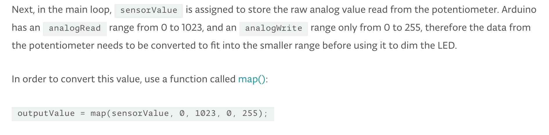
I used the map() function, which
Re-maps a number from one range to another. That is, a value of fromLow would get mapped to toLow, a value of fromHigh to toHigh, values in-between to values in-between, etc.
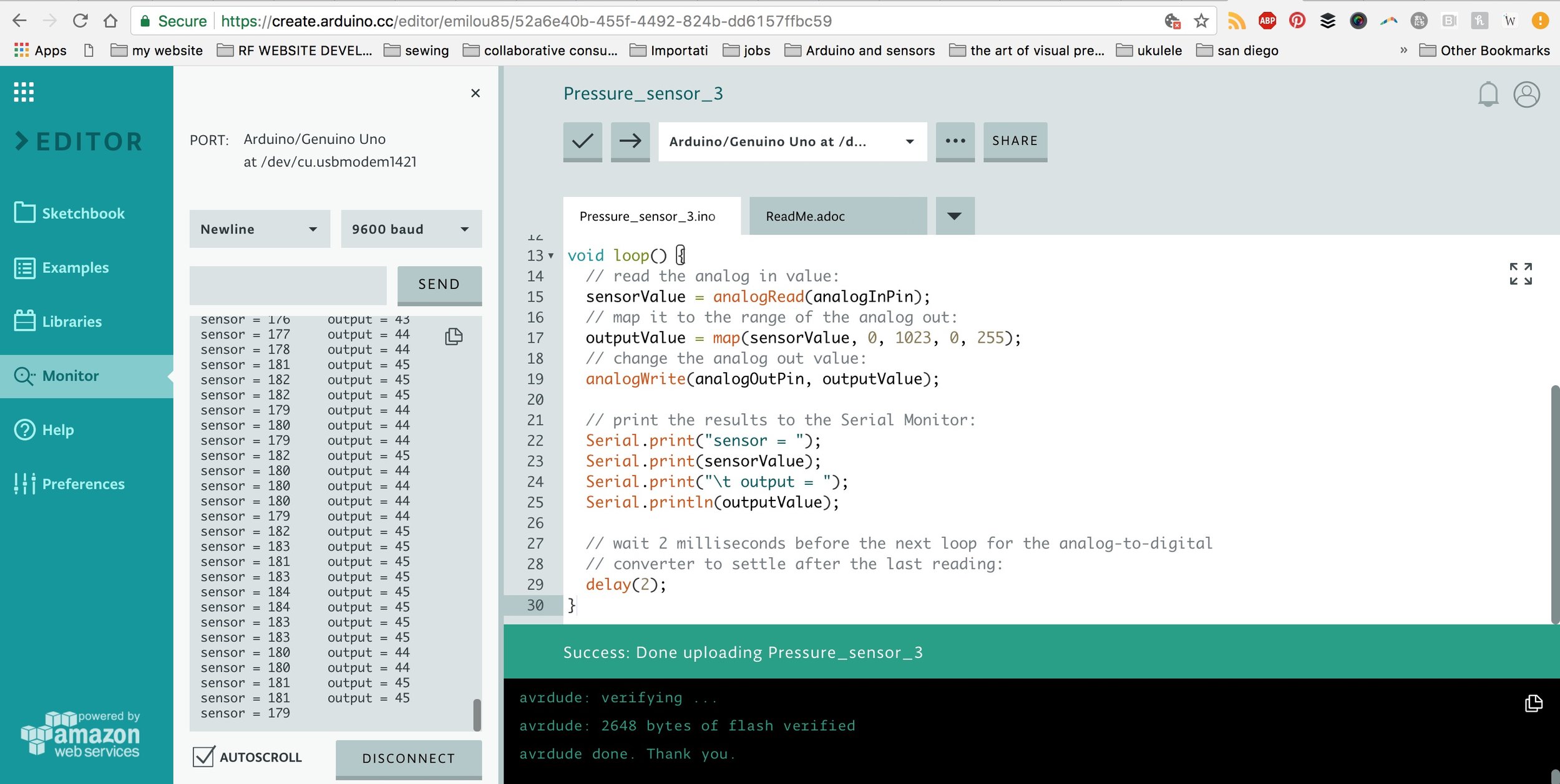
The results were satisfactory. I am now able to press the Velostat pressure sensor and get the LED to increase it's light intensity according to the pressure I apply.

RESULTS & REFLECTIONS
- I managed to obtain my desired result after a few winding steps in the process. My knowledge in regards to analog inputs and analog outputs increased exponentially.
- I still need to fully understand how the function map() works so I can reproduce my work and improve it seamlessly.
- The Arduino Web Editor works nicely and stores the projects in the same interface.
- I need to remember to READ the code I am referencing very closely, and understand WHY a Pin is used vs another one, so I can avoid waste of time like with digital Pin 7.
- After a few days of playing with different options, we found out that the Lilypad works without having to change the FTDI drivers IF, instead of putting
Tools > Board > Arduino Lilypad,
we put
Tools>Board>Arduino UNO.
The reason of tis is mysterious, but it works..
MAKING THE E-CALAVERA
INGREDIENTS
- Dark blue denim fabric
- White cotton fabric
- Felt
- Metal Snaps
- Scissors
- Turquoise Thread
- Red Thread
- 2 White Lilypad LEDs
- Conductive thread
- 3V Coin cell battery
- Velostat Pressure sensor
PROCEDURE
FELT BATTERY HOLDER
First, I made a rough battery holder prototype with denim, thread and conductive thread. It worked but the design was vey ugly and the coin cell battery was slipping out, making it easy for the circuit to short, by allowing the conductive thread on the two pieces of the denim "pocket to touch each other.
I then made a battery holder with felt, thread, conductive thread and metal snaps. I used this tutorial to make it, and it came out great.


CALAVERA DESIGN & MAKING OF
I drew a sketch of how I wanted the calavera to look like, not too complicated but with a nice simple design. I then made the pattern for the calavera in thick paper and cut it out with scissors. At this point I cut out the fabric I needed: denim for the background of the calavera, and white cotton for the skull. I sew the pieces together and was ready for the electronics.

I sew the Lilypad LEDs as eyes with conductive thread, connecting the + of the battery holder to the + of the LEDs ad to one of the Velostat pressure sensor layers. The same process was used connecting the - of the battery holder to the - of the LEDs to the other layer of the Velostat pressure sensor. The key is to NOT overlap the sewing paths, or else the circuit will short.


RESULTS & REFLECTIONS
- Planning the design of the calavera in advance and taking a rigorous step-by-step approach was very useful in making sure the final product came out nicely.
- I indeed made a small mistake in sewing the circuit, which made the LED stay on when not pressed while it turned off when pressed. Next time I will have to hook up the - of the battery to the + of the LEDs
- In this case I didn't use the micro controller, as I wanted to use it in the second step, with the ATTiny.
ADDING THE ATTINY

INGREDIENTS
- ATTiny
- Breadboard
- Arduino UNO
- Coin cell
- Pressure Sensor
- LED
- Vibration Motor
- Conductive Thread
- Hook up wires
- Breadboard
PROCEDURE
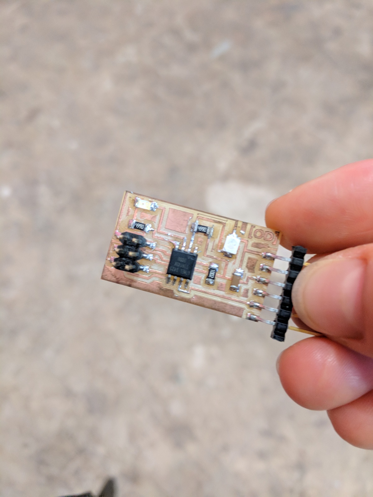
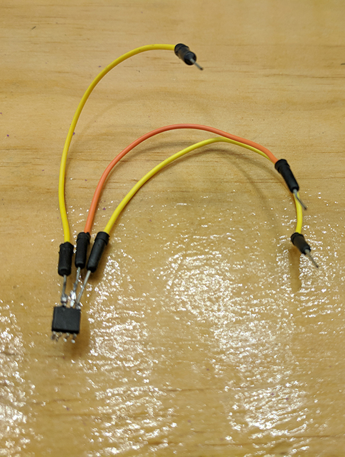
ATTEMPT 1
We didn't have a new ATTiny, yet one already soldered on a circuit board. So the first thing I had to do was to unsolder the ATTiny from the board, so I could use it in my circuit. Problem is.. Once I finally unsoldered the ATTiny from the board, I started soldering its legs to hook up wires and one leg broke :(


RESULTS & REFLECTIONS
Please find here a link to the Arduino code.